Velodyne Lidar Commissioning
This week, Summit Embedded turned around a quick project to help a client set up a Velodyne VLP-16 LIDAR unit.
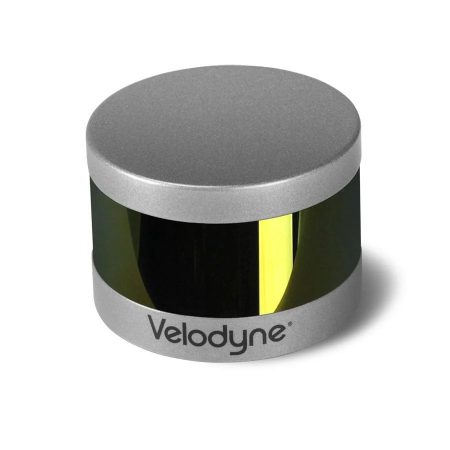
The client had purchased a used VLP-16 unit for their project. They asked Summit to wire up & test the unit. This is a straightforward task, but the client’s engineers were busy with other tasks at the time. They knew Summit is a one-stop-shop that can just dive in and get this task done. The requirements for this project were just two sentences: “Here is a LIDAR unit. Please hook it up and test it out.”
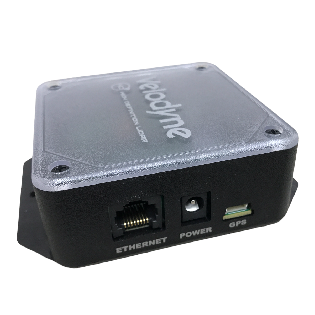
The device had an IP67-rated M12 8-pin round connector on it, but did not include a Velodyne LIDAR Interface Box. VLP-16 LIDAR units contain wires for power (12V) & ground, ethernet, and GPS Pulse/Receive (optional). The Interface Box breaks out the power/ground to a standard 2.1x5.5mm barrel jack, ethernet to a standard RJ45 ethernet jack, and GPS to a 6-pin JST header connector. We began by sourcing this interface box. While this interface box is not mandatory, it is the simplest way to connect the LIDAR to a network, as long as the interface box can be placed in a clean, dry environment (inside a vehicle’s cabin).
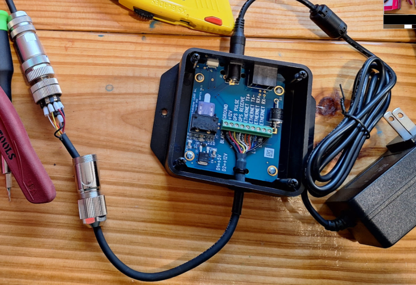
The customer wanted to retain the M12 8-pin connector so that the cable could be easily routed from the sensor (outside the vehicle) to the interface box (inside the vehicle). Thus, we also sourced the opposite gender M12 8-pin connector with matching A-key and wired it to the pigtail on the Interface Box.
Velodyne VLP-16 units usually ship with a default IP address of 192.168.1.201 and broadcast packets to 255.255.255.255 port 2368. However, some of the previously-used devices had been modified to have a different IP address. This is an example of why the client contracted Summit Embedded for this task. Commissioning a new device never goes as planned! There is always some unforeseen hang-up.
In this case, it was a simple matter of opening Wireshark to check for traffic on the correct Ethernet interface of the PC:

The source IP was 10.2.100.56 rather than the default. The packet length matches the 1248 bytes expected from a VLP-16, and so does the source port of 2368. Another notable change is that the device broadcasts to 255.255.255.255 (expected) port 2372 (not expected!). This device was set up for a vehicle with multiple LIDAR devices on the same ethernet subnet. So we’ll need to be sure to use port 2372 when viewing the data later (or change the configuration back to the default).
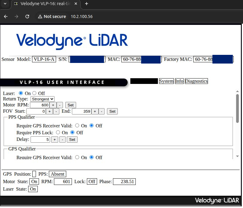
Now that we know the IP address, we can point a web browser to that IP and configure new settings as needed.
Follow Up: Wireshark Dissector
At this point, the project was complete. Summit Embedded documented the Bill of Materials, key device settings like IP address, and other helpful tips. While testing with Wireshark to see the IP address, however, our engineer noticed that Wireshark doesn’t have a .lua dissector to decode the contents of Velodyne VLP-16 packets. Sure, ROS/RViz, LidarView, and other applications can visualize the data in a better, 3-dimensional format. But those tools do require a fair bit of configuration (from IP address & port to sensor RPM & distance validity checks). If data “doesn’t just appear” in the visualization tool, it can be hard to narrow down whether a problem lies with the device/wiring configuration, or with the PC software configuration.
For this reason, our engineer followed up after the project to create a Wireshark Lua plugin. This Wireshark plugin helps to clearly determine whether the raw data coming in on the Ethernet interface is valid or not. Notice in the Wireshark screenshot above, the UDP payload appears as just a 1206-byte array of hex data in the Data [truncated] field. This isn’t very helpful! We can see the IP address and port, but can’t see the LIDAR-specific information, such as Azimuth Angle, Distance, Intensity, Timestamp, etc.
We’re all about Open Source Software at Summit Embedded. So we’ve shared our velodyne_vlp16.lua Wireshark plugin on our GitHub account under a GPL license: https://github.com/summitembedded/velodyne. Let us know if you find it helpful!
Once you install it, Wireshark will show the LIDAR in more detail as shown below. The nice thing about this method is that you can click on each signal and see the raw bytes in the packet highlighted in the Wireshark pane on the right. As low-level embedded software experts, we always want to see the raw data when debugging issues!
In this case, it turned out there was an issue with the first sensor we tested. It always read zero meters, despite have a correct configuration (Laser state = enabled, etc). The first image below is from the non-functional unit. The second image below is from a different, functioning unit.The second image also includes updates to the Wireshark dissector to sort the entries based on physical laser order (vertical angle). The actual order of the bytes in the packet hop around. This is because the individual lasers fire in a non-sequential order to prevent one sensor reading the return of an adjacent beam.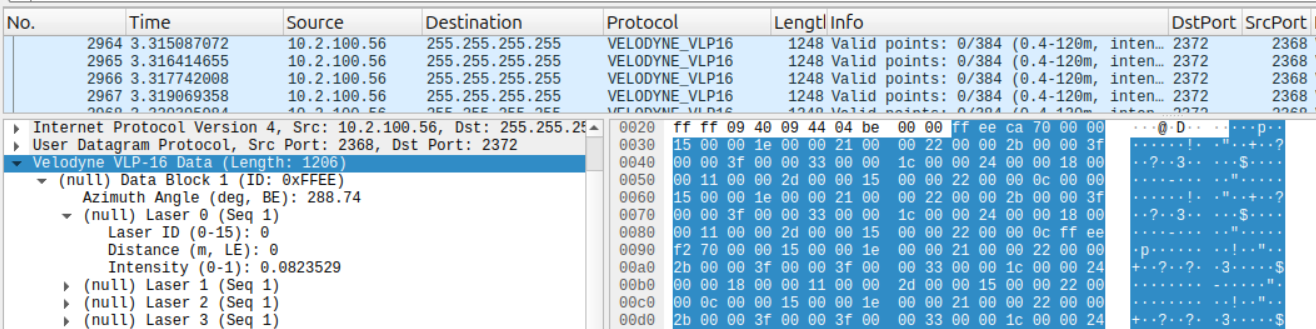
Non-functional sensor that always read a distance of 0m
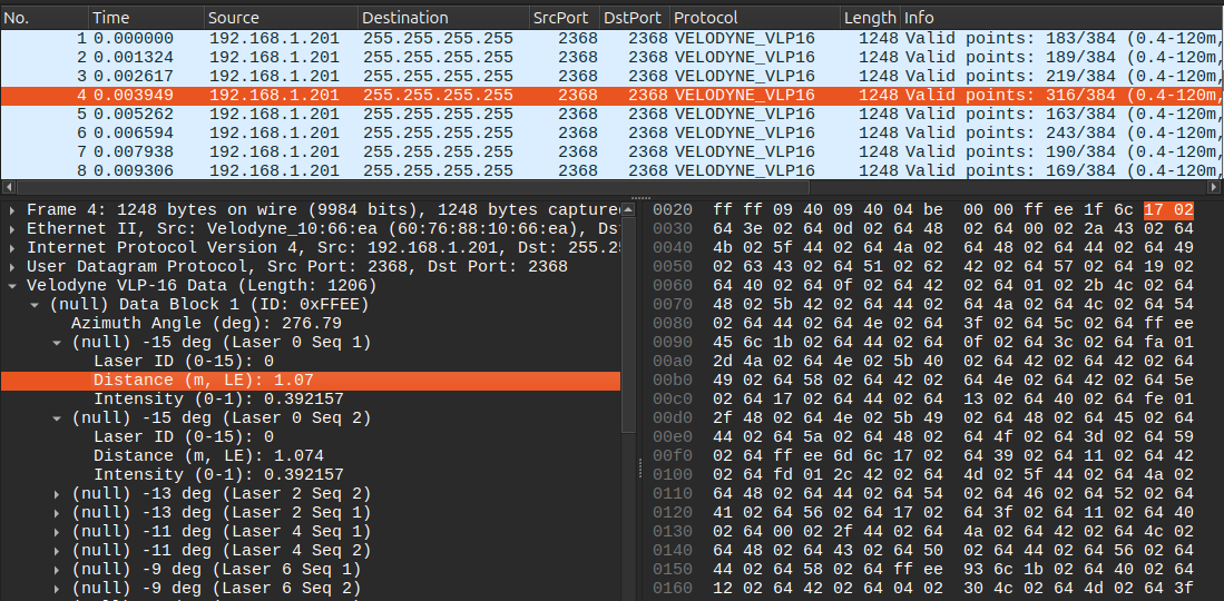
Working sensor that read varying distances